Enchanted Rose 2.0 with Falling Petals
Got a performance of Beauty and the Beast coming up? For about $200, you can build this Enchanted Rose with Falling Petals.
Dropping The Petals
There are a few approaches to make the petals drop. You’ve got a microcomputer (a Raspberry Pi) which can send electrical current HIGH or LOW on an output pin. How do you translate that into petals physically dropping on command?
In version 1.0, I used servo motors to pull fishing line. That fishing line was attached to a spring-loaded magnet in the bud of the rose. When the fishing line was pulled, the magnet would retract into the bulb and drop the petal. This worked very well, but it’s a delicate mechanism and wouldn’t ship well, and I wanted the 2.0 design to work for shipment.
After horsing around with solenoids (which didn’t work very well because they (a) were too bulky and (b) weren’t strong enough), the design I ultimately settled upon was to use individual, cheap 6v air pumps to push air through a small opening, and blow out a toothpick, to which a petal was attached. I found that I could “overclock” the air pumps at 12V (higher than rated) to push slightly more air out than rated. As long as the rose petals remained relatively light, bingo, it works. Here’s an in-progress video:
Here’s an earlier video showing mock petals which were much lighter — tissue paper:
Design Goals
- Drop 4 petals on cue, one by one
- Turn on and off stem lights
- Turn on and off accent lights, set color
- Easy to reset between productions
- Wireless — allow to be set on a pedestal on stage
- Control via mobile web browser
- Durable enough to ship
- Do NOT require that it connect to a local internet
- Easy to use interface that an elementary school stage crew could use
- Easy on-site setup. Ideally, just turn it on and it works.
Parts List
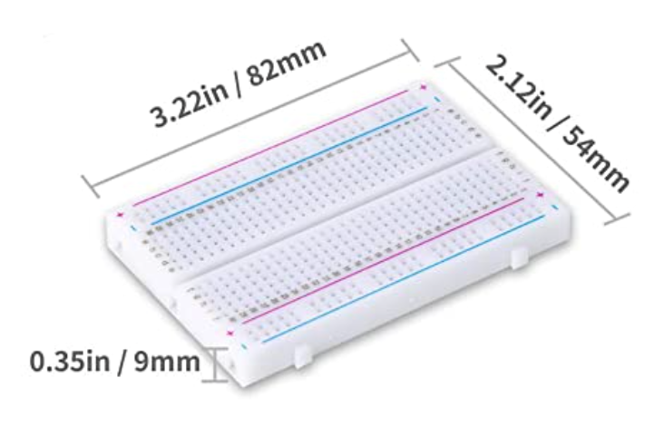 | 2 half breadboards |
|---|---|
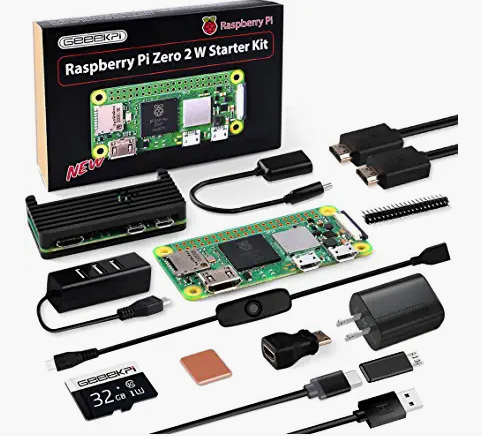 | Raspberry Pi: I used a Raspberry Pi Zero 2W, but any Raspberry Pi which has onboard wifi will work, such as a 3B+, 4, Zero W, etc. Do not choose a Pico; that’s a different product line. You’ll also need a MicroSD card to store the operating system. |
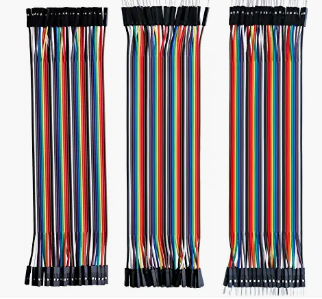 | Jumper wires |
 | Cloche: This was the widest and tallest one I was able to find for easy ordering. But I really did prefer the one I was able to find for the 1.0 build 4 years ago. This one is just barely big enough. Shop around — you may have better luck finding a wider one in a local arts and crafts store. You really want one that is fairly wide, because the petals need to fall freely and not get hung up against the side. |
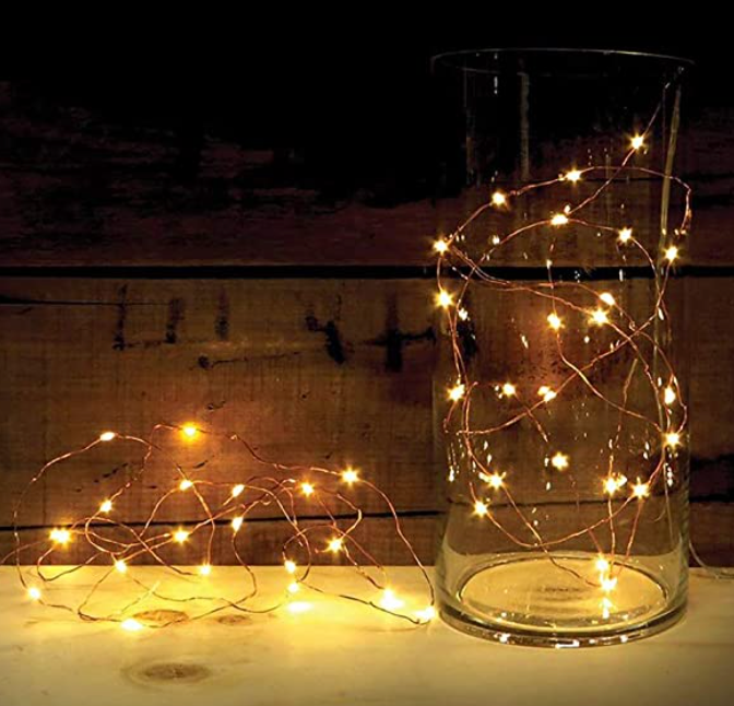 | Stem “fairy” lights |
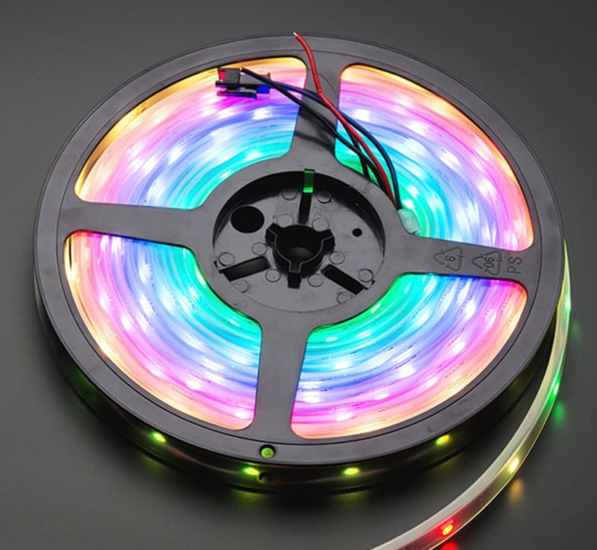 | Neopixel lights |
 | 11 AA batteries |
 | One 8-AA battery pack |
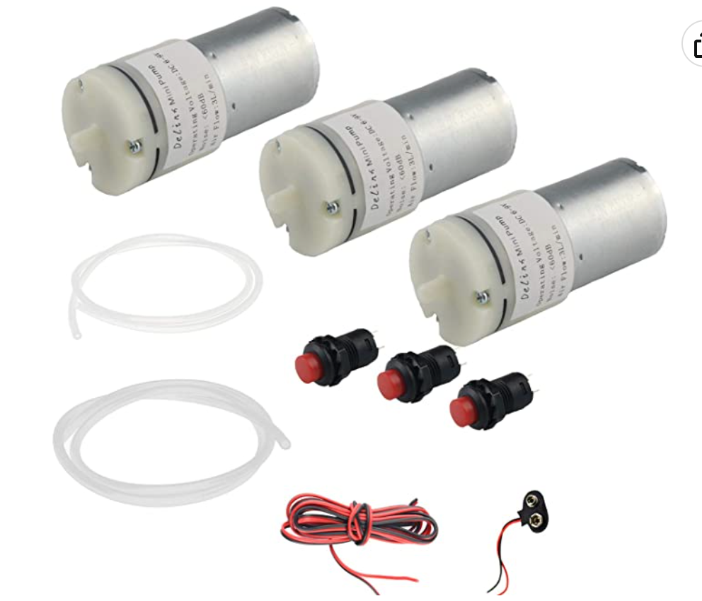 | 4 pumps and tubing (you’ll need 2x of these three) |
 | Enchanted Rose with silk petals – look for lightweight petals. The standard one on Amazon is too heavy — I went to Etsy to shop for mine. |
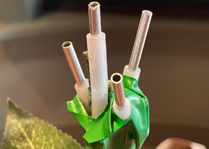
 | Toothpicks — You are looking for ones which slide in and out of the aluminum tubing very easily, but which also block the most amount of air (to build up pressure — you need some force on these to pop the petal.) |
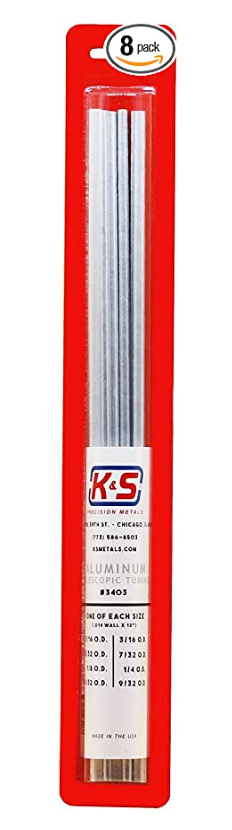 | Aluminum metal tubing (small) — The purpose of these aluminum tubes is to eliminate a lot of friction that existed between the toothpick and the pneumatic tube. In other words, toothpicks and these tubes sort of act like a blowdart. By using aluminum tubing as a gasket within the pneumatic tubing, a lot of the friction is reduced. |
 | heat shrink |
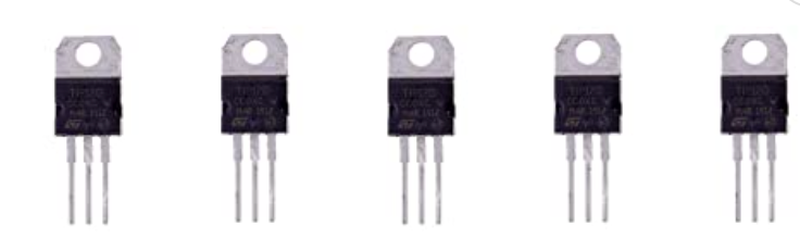 | 5 Transistors: [TIP102] |
| Soldering iron, solder and flux | |
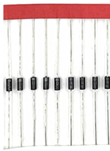 | 4 Diodes: 1N4004 or MUR340 |
| 3.3v to 5v level converter: 74AHCT125 | |
| Coat hanger | |
| Cigar box or wooden box for the base componentry | |
| Wire clippers | |
| Drill and bits | |
| Hot Glue Gun and Hot Glue | |
| Multimeter (helpful but not required) | |
| Cigar box, wooden box or other case for components below the cloche | |
| Pipe insulation foam for vibration-dampening, to just fit around the pumps |
Before You Begin
You’ll want to get your Raspberry Pi set up with Raspbian OS on a micro-SD card. Make sure you have SSH access to your RPi. You might also want to set this up to present its own SSID/wifi network. I’ve got a blog post on that here.
If you’re new to Raspberry Pi, here’s one video to get you started in setting up the operating system and SSH:
I also loved using Visual Studio Code’s “SSH” remote features. Setting this up can be a tiny bit tricky, but stick with it. Once you get this working, it’s incredibly productive. It allows you to use your desktop (Mac, Windows or Linux) to work with files and directories on your RPi.
NeoPixels will also require ROOT-level permissions on your Raspberry Pi to install some drivers. Now, there are all kinds of security folks telling you that using root on your Raspberry Pi is a bad practice for stuff like this. But since this is a simple stage prop, I had no problem with the idea of just using my root user and a password for the entire build, and it saved a lot of file permission headaches to just be “root” and be done with it:
sudo passwd rootSet a password for the root user, reboot your pi, and connect in as root from then on. While it may not be “best practice” for security, trust me, you’ll save a lot of headaches with installing libraries etc.
Assembly
There’s both a hardware circuitry part and a software part. Let’s get some of the basic circuitry working first.
For ease of explanation, the hardware components can be thought of as three different “zones,” all powered by a single Raspberry Pi. These zones don’t need to talk to one another, except that all ground wires should be connected together and also to the RPi’s GND pin.
There are two zones powered by 4.5V: The Fairy lights and the Neopixel lights. There is one zone powered by 12V: the pump zone.
(DO NOT power the Neopixel lights with the 8 AA batteries (12V) used to power the pumps, as you will permanently damage the Neopixels!)
Zone 1: Control the stem lights (4.5V)
Let’s start here, because it’s the easiest circuit. These fairy lights are controlled by 3 AA batteries (4.5V.) You want to be able to have a GPIO pin on the Raspberry Pi toggle tell a transistor to allow current to flow to power these lights.
Cut the fairy light wire, and strip the ends. It’s a bad idea to power the LED directly from the Raspberry Pi, as altogether, the current draw might be more than the Pi can handle. So, you’ll want to use a standard Transistor (like a TIP 102) to switch the current.
Now, run a wire from the GPIO pin of choice — I chose pin 25 (BCM) — to the “base” pin of the transistor. When this is toggled HIGH, it will close the circuit of the LED fairy lights and thus turn them on or off programmatically.
[CIRCUIT DIAGRAM HERE]
Zone 2: Control the 4 pumps (12V)
The main mechanism to drop these petals is to blow air through tubes which have loose petals. I chose to cut some aluminum tubing to reduce the diameter of airflow and also to reduce the friction with the wooden toothpicks:

For the electronics, you need a diode for each of the 4 pump circuits, for the reasons described in this video (where this video says “solenoid”, substitute in the “pump” in your mind — the same principle applies):
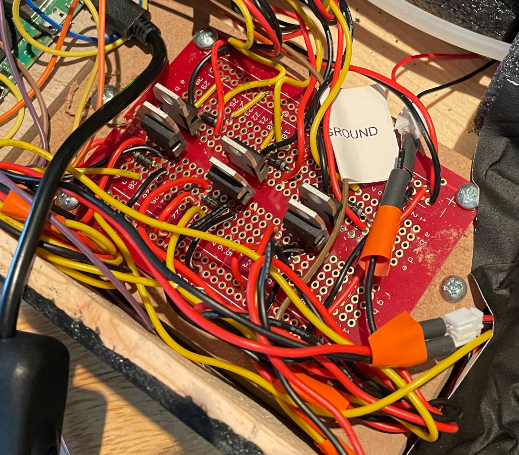
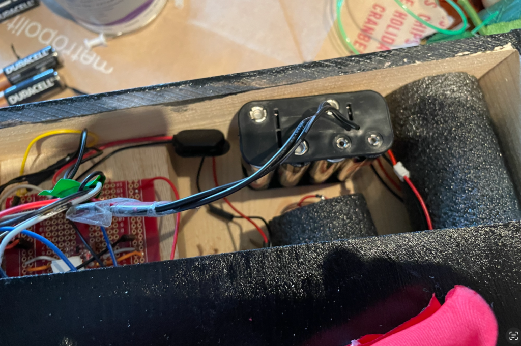
In my Enchanted Rose prop, I built a breakout board with a bunch of these MOSFET transistors and diodes. I overbuilt this board, making it with 6 different circuits when it only really needed 4. It’s messy looking, but pretty simple. Each of these circuits has a MOSFET transistor and a diode. Take care to get the direction of the diode correct — it needs to be pointing toward the positive load. (A diode is rather like a backflow valve in plumbing — it allows current to flow in only one direction, toward the “ring” on the diode.) The yellow wires in this photo below come from the Raspberry Pi (GPIO pin) and when they are HIGH, they allow current to pass from the “Base” of the transistor to the “Emitter.”
Basically you want four circuits which allow the GPIO pins on the RPi to turn on and off the motor. A single such circuit looks like this. (Note that instead of a 9V battery, I “overclocked” it with a 12V battery pack — I found these pumps can handle short bursts of 12V.)
Each pump motor needs a circuit like the below. Since RPi cannot output 9V, we’ll make use of a transistor to switch a supplied 9V current on and off. (Note that in production, I ended up boosting the power supply to 8 AA batteries, or 12V. The motors can handle this higher voltage for short duration, even though they’re rated for 6-9V.)
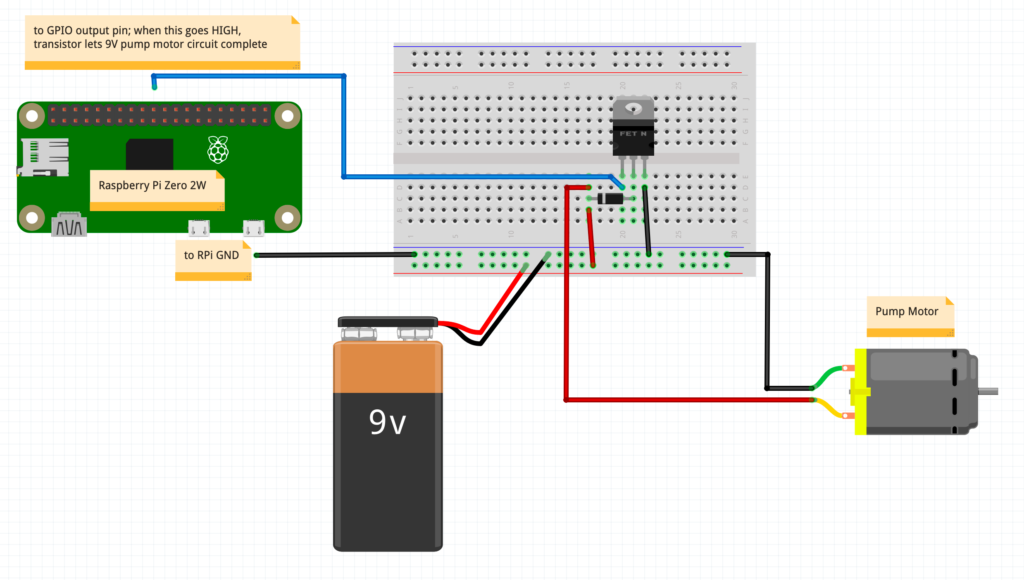 Wiring diagram for pump motors
When you make six such circuits on a PCB board and don’t spend too much time cleaning up the build, it looks like this:
I chose Broadcom pins 21, 26, 6 and 5 to control the air pumps, as the python code shows.
I cut insulation foam for these motors (pipe insulation) which helps reduce the vibration sound a bit.
Since these motors generate current spikes when they are powering down and powering up, it’s very important to protect your RPi with a diode, as follows (the directionality matters! pay attention to the line on the diode and the positive lead from the motor):
Zone 3: Control the Neopixel accent lights (4.5V)
DO NOT POWER THE NEOPIXEL WITH ANYTHING GREATER THAN 5V, AS YOU WILL PERMANENTLY DAMAGE THEM.
The python code to control the Neopixel needs a set of libraries called “CircuitPython” to work. You’ll need to follow the NeoPixel Adafruit guide to installing CircuitPython.
I strongly recommend you read through the NeoPixel to Raspberry Pi Wiring Guide on Adafruit, which is likely to be more up-to-date than anything I’m providing here. I went to a 74AHCT125 level-shifter chip to map the Raspberry Pi’s 3.3v output to proper 5V levels. Note that the power cord shown in the diagram below simply feeds out to the 4.5V battery pack. The ground rail needs to be connected to the RPi’s ground rail. All the grounds in this project all connect together, and connect back to the Rpi’s ground. You can and should run both the LED fairy lights and the Neopixels off the same battery pack.
Then, check out the “neopixel_control.py” code that I put up on Github.
Software
I’ve published two Github repos that should really accelerate your work here.
First, let’s run through what you need, because it’s helpful to see this at a high level. If you want to go the easiest possible route, set your RPi to render its own wifi network, and make sure you configure your Raspberry Pi so that it is known as 196.168.11.1 on its own wifi network; that’s what the software is built for.
You will need the following software components set up:
- Software to tell the GPIO pins what to do and render it as an “API” which can be called. That’s the purpose of this Enchanted Rose Flask API Repository on Github.
- Website software to deliver a nice user interface so that people don’t need to call an API directly to change the lights, drop the petals. See this Next JS Front-End Repository on Github. Run this on an Apache web server on the Raspberry Pi. To do this, set up an Apache Web Server on your Raspberry Pi. Make sure it’s working by visiting the IP address of your Raspberry Pi from a web browser. Next, take the “out” folder from the repository above, and place it in your Raspberry Pi’s /var/www/html folder. You should then have a web front-end that is calling locally to the device’s Flask port (hardcoded in the source as: http://192.168.11.1:5001).
- Set up the web server and the API, and make sure they start properly at Raspberry Pi boot-up.
- Make your Raspberry Pi its own local wifi network, so you don’t have to rely upon tapping into the router or a network wherever your production happens.
Configuring Raspberry Pi for “Ad Hoc Network”
Now, how do we get a mobile phone to reach the Raspberry Pi? Of course, if we know the networking details at the production venue, we could in theory just have the RPi join the wifi network of the theatre, and then somehow go to the theatre’s router settings and look for its address. But that’s a pain and doesn’t scale well.
So I was excited to hit upon the idea of having the prop create its own “Ad Hoc Network” (i.e., it’s own Wifi SSID that you can join.) Not only does this eliminate the need to have the stage manager at each playhouse somehow find a way to connect the prop into their own local network, but it removes any requirement for a display or keyboard to ship with the device for configuration purposes.
All they you to do is plug in the device, wait for boot-up, and it presents its own Wifi Network (“EnchantRose”.) You then simply enter the password, bring up a web browser on their phone, and visit a pre-determined IP address which I’ve configured: http://192.168.11.1.
It took a while to figure out how to configure Raspberry Pi to do this, since the instructions have changed seemingly with every release of Raspbian, the RPi operating system. But I figured it out by adopting existing instructions, and blogged about it here. The steps in that blog post provide all you need to do to get your Raspberry Pi setting its own network. To ensure the Enchanted Rose repository code works, be sure to set your network to the instructions given — you want the RPi to be able to reference itself on its own network as 192.168.11.1.
What’s most exciting about this is that it’s a pattern that can has many applications in the world of “Internet of Things” — run Apache2 on your Raspberry Pi to host a website, and render that website visible via the Rpi’s own password-secured wifi network.
Current Status
The new version 2.0 prop is fully functional. I’ve sold it and shipped it to one of the many production managers who have inquired. As this post continues to get indexed by Google, I get hit up for these builds; at this writing it’s over a dozen such requests, from FL, CA, HI, UK, NJ, CO and more.
UPDATE, late January 2023: This 2.0 prop is sold to a production in Hawaii, and has been shipped off.
I’ve decided for now that the logistics and expense of shipping these out to productions is just too complicated, but I’d love to hear from you if you’ve built one of these. If you’ve got specific questions on assembly or the software, drop me a note. On with the show!


Just wondering how to connect the fairy lights to the breadboard with the transistor. Mainly just wondering if there was a diagram to look at, I’m of a visual learner and don’t know too much about this stuff.
Hi Luke — you might find this video helpful. Basically, the transistor simply acts as a switch. https://www.youtube.com/watch?v=CD9-oPzJL0I