
Read Propane Levels from Anywhere with Home Assistant and an ESP32

This is an update to my post from July of 2022, Internet of Things: How to Remotely Monitor Propane Tank Level via Raspberry Pi, using a much better, cheaper architecture. Instead of using a dedicated RPi that logs things to Azure, I’m using the much more affordable and lower-power-consuming ESP32 board as the sensor. The board costs less than $10! It can also be put to low-power “deep sleep” on whatever interval you’d like. And it sends its data via MQTT to Home Assistant. Home Assistant then does the visualization, and optionally, whatever historic logging you’d like. Before continuing, you might want to read the first attempt here, which explains a bit more about how these gauges work, and outlines a massive-overkill approach.
Background: Why?
We’re building a second home, which has a buried 250 gal propane tank for the grill and an outdoor fire table. I wanted a convenient way to monitor propane levels. Wouldn’t it be great to be automatically notified when propane levels fall below, say, 20%, nudging me to order a delivery refill?
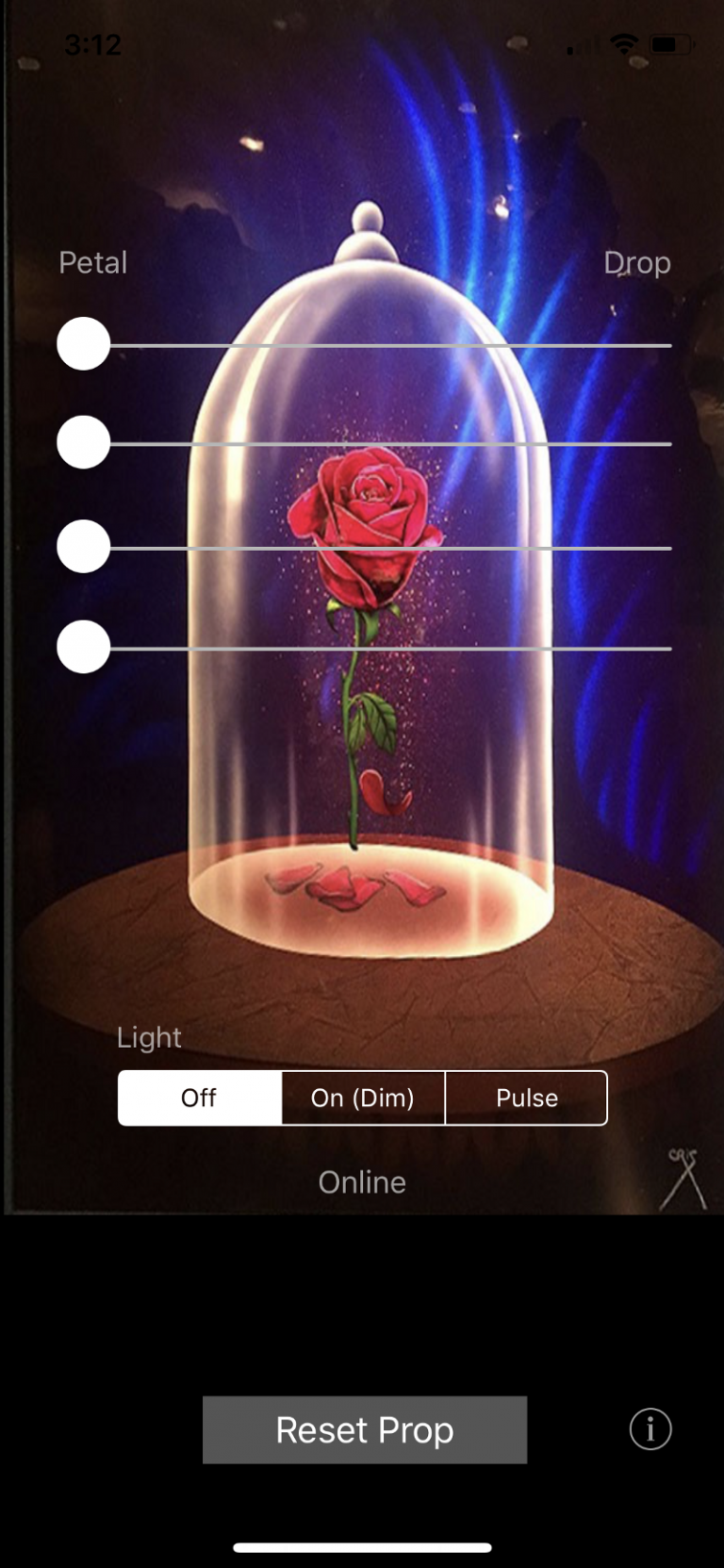
Ideally, I’d be able to grab my iPhone, and glance at the propane level in this tank, and even inspect a log to see if there’s a slow leak in the system, or which use-cases draw the most propane down.
Why not commercial?
There are commercial products available which do this, but many of them start at $200, and are often tied to refill services. Several of them even require a monthly subscription.
With just a couple of off-the-shelf components, I was able to build a working system for just $30 or so, with no monthly subscription. This isn’t counting my pre-existing Raspberry Pi 4 (~$70) which capably runs the open source Home Assistant software.
Correction: I say in this video that WiFi interferes with analog-to-digital chip 1 (ADC_1), but actually, it interferes with ADC_2, not ADC_1. Choose a GPIO pin that’s in the ADC_1 collection for the V4 board if you want to do analogRead(); The code below is correct.
CAUTION: BEFORE UNDERTAKING THIS PROJECT, know that working with highly explosive propane and electricity is very dangerous. Even though we're only using 3.3V, be sure to fully seal the reader, using silicone caulk, liquid rubber sealant, or the equivalent. Do this project at your own risk. Maker assumes all responsibility. Void where prohibited, etc.
Espressif 32 Boards: Wow!
It was Arduino which opened up the world of microcontrollers (beyond college EE classes) back in the early 2000’s. By 2005 or so, I switched over to Raspberry Pi boards for more power, plus the ability to use Python. Happily ensconced in the Raspberry Pi (RPi) world for a decade or more, I didn’t really keep up with the wide range of microcontrollers based upon the Arduino toolset.
And wow — now that I’ve resurfaced to look around — the ESPRESSIF 32 series of microcontrollers is amazing.
You get things like 2 fast-running cores, plus Bluetooth plus Wifi, plus “deep sleep” mode, analog-to-digital converters and more for under $10! They are ideal for sensor-reading applications, and Internet of Things (IoT) solutions.
The ESPHome project beautifully and seamlessly links Home Assistant to ESP32 boards and sensors of various kinds, providing an easy-to-use platform. I could have gone this route (had I known about ESPHome at the time, which I didn’t!) but am glad I didn’t, because I now better understand all the steps in the process.
Here’s the ESP32-DevKit board I used: the ESP-32-DevKit V4. These things come with two CPU cores, a bluetooth board, on-board wifi, two analog-to-digital readers (ADC), and more than a dozen General Purpose Input-Output (GPIO) pins. And you can buy 3 of them from Amazon for less than $17! I’m blown away. What a world we live in.

Here’s what you’ll need:
- ESP32 Development Board: I used ESP32 Development Board V4, and Arduino IDE. You could also go with a non-“development board”, if you’re happy soldering the outputs/inputs directly. “Development board” simply means it comes with attached headers.
- Hall Effect Sensor (less than $5 for a pack of ’em) [edit, Mar 1 2025 — I just heard from a reader that this link leads to a 404… try THESE Hall Effect Sensors]
- Propane “Remote Ready” gauge ($9; does not include the hall effect sensor or wire.)
- Home Assistant: I have mine running on a Raspberry Pi 4. Must be on the same network you’re connecting your ESP32 to.
- Wifi coverage within reach of your ESP32 board
- A cabinet barrel style magnet or other magnet — needed only for building, not deployment. It’s very handy to be able to forcefully set your gauge to various levels to check readings, and to calibrate the gauge.
- Wire, solder, soldering iron, breadboard (optional)
- Some way to power your board (a solar panel with a battery charger is a good approach, and, while this add-on is easy to implement, it’s beyond the scope of this post. In my case, I happen to have PVC conduit running to the propane tank from the garage, and will likely send 3.3V over a long micro-usb cable through that conduit.)
- Project enclosure
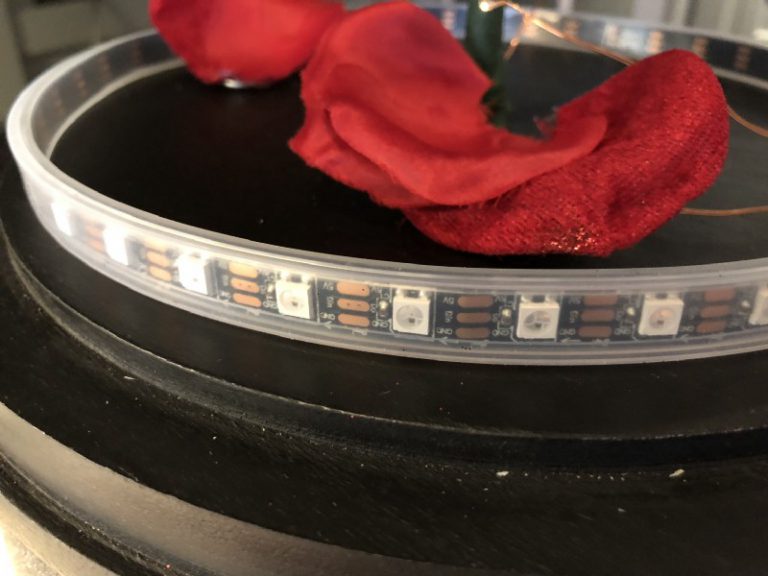
Let’s start with the plastic gauge itself. You need to get a Hall Effect sensor oriented properly in there to read the magnetic values. To do so, gently slide off the black plastic “Remote Ready” protector of your “Remote Ready” gauge. You’ll eventually want to hot-glue the Hall Effect sensor in place, but finding the proper placement for accurate 0-100% readings is finicky. It’s perhaps the trickiest bit of this project.
As I recall, you’ll want to put the flat side of the Hall Effect sensor facing down, and get it flush as far toward the center of the dial as possible. Don’t worry if you don’t get good (or even any) signal on the first try — keep trying, changing the position of the Hall Effect sensor as you go. You’ll find a configuration that works eventually. I needed to try several different positions for this first, using scotch tape temporarily, to ensure that the sensor was reading values no matter where the dial was set.
As shown in the video, I found a small cabinet closure magnet extremely helpful to have on hand for this part of the project.
Then, once the Hall Effect sensor was in the correct position, I hot glued it in place and put the “Remote Ready” black plastic clip over it. (I neglected to get a photo of this, but it’s one of those things that once it’s set, it’s set, and I don’t want to dissemble it just to show the insides.)
Code
The code is pretty straightforward. Shown below.
#include <WiFi.h>
#include <PubSubClient.h>
#include "home_secrets.h" /* wifi passwords and such */

// values in home_secrets look like this:
/*
const char *ssid = "MYNETWORKSSID"; // Enter your Wi-Fi name
const char *password = "mypassword";  // Enter Wi-Fi password
const char *mqtt_broker = "192.168.4.52";
const char *outputTopicPercentage = "propane/1/percentage";
const char *outputTopicVoltage = "propane/1/voltage";
const char *inputTopic = "propane/1/input";
const char *mqtt_username = "mqtt";
const char *mqtt_password = "mqttpasswordgoeshere";
 */

// GPIO PIN: Set to whatever GPIO pin you're using on the board
// for the data read off the Hall Effect Sensor.

// NOTE: ON ESP32 DEVBOARD V4 AND SEVERAL OTHER ESP32 BOARDS,
// WIFI INTERFERES WITH READING ANALOG VOLTAGE VIA "ADC_2".
// SO, CHOOSE AN ADC_1 PIN! 33 WORKED WELL FOR ME.

const int GPIO_PIN_HALL_EFFECT_SENSOR_READ_INPUT = 33;

#define uS_TO_S_FACTOR 1000000  /* Conversion factor for micro seconds to seconds */
#define TIME_TO_SLEEP  60        /* Seconds. Time ESP32 will go to sleep */

const int mqtt_port = 1883;

int hallEffectVoltageLevelInt = 0; // used to sum-up the readings and average them

WiFiClient espClient;
PubSubClient client(espClient);

// How the sensor works: Hall Effect sensor turns magnetic levels into a voltage value.
//
// Note that Hall Effect sensor rneadings are very sensitive to the physical orientation
// of the reader.

// in my case, the max readings are around 2369 and minimum around 1280.
// One simpler way to go is to just do a linear interpolation.

// using y=mx+b, the basic formula to map voltage to approximate percentage-full
// is:  (voltageDigital - 1280)/10.89
// max of 100, min of 0

// ...but as it turns out, the guage is not PERFECTLY linear. for instance here are the samplings -- percentages: readings
// 100: 2380
// 90: 2330
// 80: 2214
// 70: 2107
// 60: 1991
// 50: 1865
// 40: 1736
// 30: 1612
// 20: 1497
// 10: 1377
// 5: 1316


void setup() {
    // Set software serial baud to 115200;
    Serial.begin(115200);

    Serial.println("That was a nice sleep. Waking up.");

    pinMode(GPIO_PIN_HALL_EFFECT_SENSOR_READ_INPUT, INPUT);

    // Connect to a WiFi network
    WiFi.begin(ssid, password);
    while (WiFi.status() != WL_CONNECTED) {
        delay(500);
        Serial.println("Connecting to WiFi..");
    }

    Serial.println("Connected to the Wi-Fi network");
    //connecting to a mqtt broker
    client.setServer(mqtt_broker, mqtt_port);
    client.setCallback(callback);
    while (!client.connected()) {
        String client_id = "esp32-client-";
        client_id += String(WiFi.macAddress());
        Serial.printf("The client %s connects to the public MQTT broker\n", client_id.c_str());
        if (client.connect(client_id.c_str(), mqtt_username, mqtt_password)) {
            Serial.println("Public EMQX MQTT broker connected");
        } else {
            Serial.print("failed with state ");
            Serial.print(client.state());
            delay(2000);
        }
    }
    // Publish and subscribe
    //client.publish(outputTopic, "");
    client.subscribe(inputTopic);


    // STEP 2: READ VALUES, AVERAGE THEM, AND REPORT TO MQTT

    int sum = 0;
    Serial.println("Reading 100 values so I can average them...");
    for (int i = 0; i <= 100; i++)
    {
       int val = analogRead(GPIO_PIN_HALL_EFFECT_SENSOR_READ_INPUT);
       sum = sum + val;
       delay(50);
    }

    // now get the average
    double averageRead = sum / 100;

    Serial.println("Average voltage read (digital representation, is not an actual voltage level):");
    Serial.println(averageRead);

    // if you wanted a simple interpolation you might use something like:
    // double myValue = ((averageRead - 1280) / 10.89);

    int volts = int(averageRead);
    int interpolatedValue = getPercentageByVoltage(averageRead);
    if (interpolatedValue > 100) {interpolatedValue = 100;} // cannot be greater than 100
    if (interpolatedValue < 0) {interpolatedValue = 0;} // nor less than zero

    Serial.println("INTERPOLATED VALUE");
    Serial.println(interpolatedValue);

    // Now send these values out via MQTT
    char msg_out[32];
    sprintf(msg_out, "%d", interpolatedValue);
    Serial.println("Sending myValue to MQTT:");
    Serial.println(interpolatedValue);

    client.publish(outputTopicPercentage, msg_out);

    sprintf(msg_out, "%.0f", averageRead);
    client.publish(outputTopicVoltage, msg_out);

    client.loop();

    Serial.println("Good night. Going to sleep.");


    // STEP 3: PREPARE FOR SLEEP
    // close mqtt client
    delay(1000);
    client.disconnect();
    delay(1000);
    WiFi.disconnect(); //disconnect from the MQTT broker

    // STEP 4: SLEEP
    esp_sleep_enable_timer_wakeup(TIME_TO_SLEEP * uS_TO_S_FACTOR);
    esp_deep_sleep_start();

}

// This function, callback, is not currently used, but this is what's
// called if the ESP32 device RECEIVES an MQTT message on the
// inputTopic MQTT channel

void callback(char *topic, byte *payload, unsigned int length) {
    Serial.print("Message arrived in topic: ");
    Serial.println(topic);
    Serial.print("Message:");
    for (int i = 0; i < length; i++) {
        Serial.print((char) payload[i]);
    }
    Serial.println();
    Serial.println("-----------------------");
    // do something with it here
}

/* Interpolation table */

int voltage[] = {0, 1287, 1294, 1301, 1316, 1328, 1340, 1352, 1364, 1377, 1389, 1401,
1413, 1425, 1437, 1449, 1461, 1473, 1485, 1497, 1509, 1521,
1533, 1545, 1557, 1569, 1581, 1593, 1605, 1612, 1624, 1636,
1648, 1660, 1672, 1684, 1696, 1708, 1720, 1736, 1749, 1762,
1775, 1788, 1801, 1814, 1827, 1840, 1853, 1865, 1878, 1891,
1904, 1917, 1930, 1943, 1956, 1969, 1982, 1991, 2003, 2015,
2027, 2039, 2051, 2063, 2075, 2087, 2099, 2107, 2118, 2129,
2140, 2151, 2162, 2173, 2184, 2195, 2206, 2214, 2226, 2238,
2250, 2262, 2274, 2286, 2298, 2310, 2322, 2330, 2335, 2340,
2345, 2350, 2355, 2360, 2365, 2370, 2375, 2380, 100000};


int getPercentageByVoltage(int voltsIn) {
  int percentageIndex = 0;
  while (voltsIn > voltage[percentageIndex]) {
    percentageIndex++;
  }
  return percentageIndex;
}


/* Since we're using the deep sleep pattern, we don't need or use the loop routine. */


void loop() {

}Code language: PHP (php)
Home Assistant
To read the value, you’ll need some way to read the values from MQTT. I’m running the excellent Home Assistant, which has an easy-to-setup MQTT integration. You simply define the sensor value in HA’s “configuration.yaml” file, and then you can create display cards for them:
Defining the Sensors
# configuration.yaml entry which defines a Home Assistant sensor from MQTT
mqtt:
  sensor:
    - name: "propane_tank_1_sensor_voltage"
      state_topic: "propane/1/voltage"
      value_template: "{{ value }}"
      unit_of_measurement: "units"
    - name: "propane_tank_1_percentage"
      state_topic: "propane/1/percentage"
      value_template: "{{ value }}"
      unit_of_measurement: "%"Code language: PHP (php)
Displaying the value

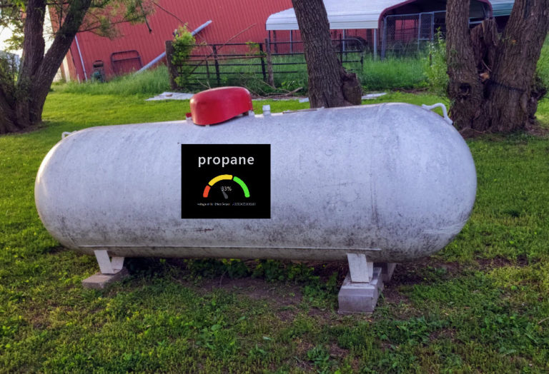
type: gauge
entity: sensor.propane_tank_1_percentage
needle: true
unit: '%'
name: Propane Level
severity:
  green: 40
  yellow: 20
  red: 0Code language: JavaScript (javascript)
And that’s it! Now I can add these values to automations in Home Assistant, so (for instance) it will push-notify me once every 48 hours when the propane tank levels are below 20%.
Got a Smaller Tank?
This post was focused on a buried 250 gallon tank.
Are you interested in measuring propane levels in smaller, portable tanks? You might be more interested in a weight-based sensor. If you’re in this camp, here’s an interesting video to consider: Measure Propane, CO2, Salt, and so much more with this DIY MQTT Weight Sensor using Tasmota (youtube.com)


You must be logged in to post a comment.