
Building a Water Tank Monitor for an Off-Grid Wellhouse
I built a water tank measuring system using two ESP32 LoRa devices. Here’s how it works.
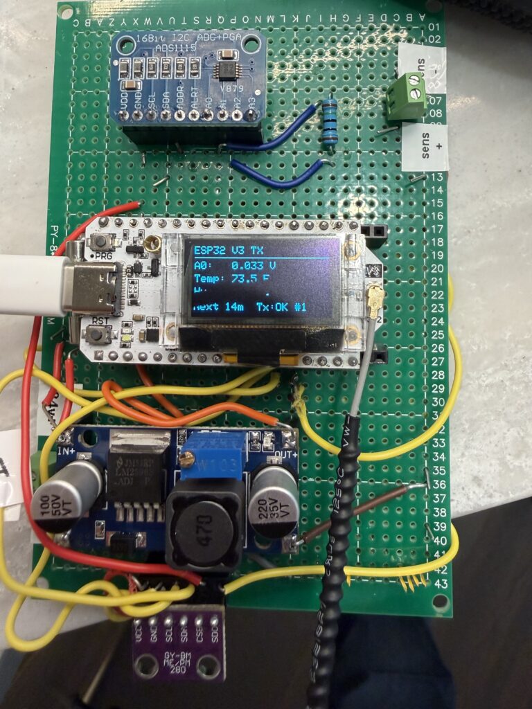
I built a water tank measuring system using two ESP32 LoRa devices. Here’s how it works.
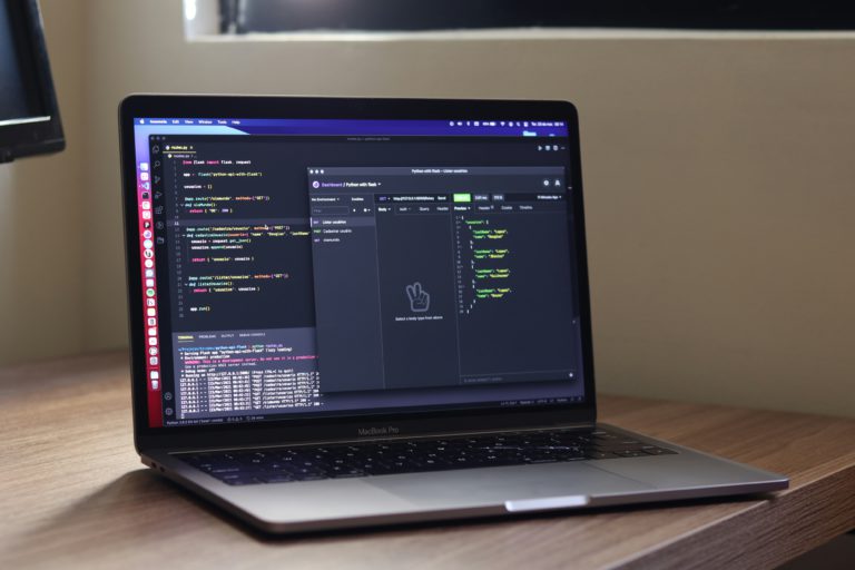
RapidAPI makes it easy to monetize the application programming interfaces you’ve built.

Remotely read a liquid propane gas (LPG) tank with a cheap ESP32 board, Raspberry Pi and a little cleverness.
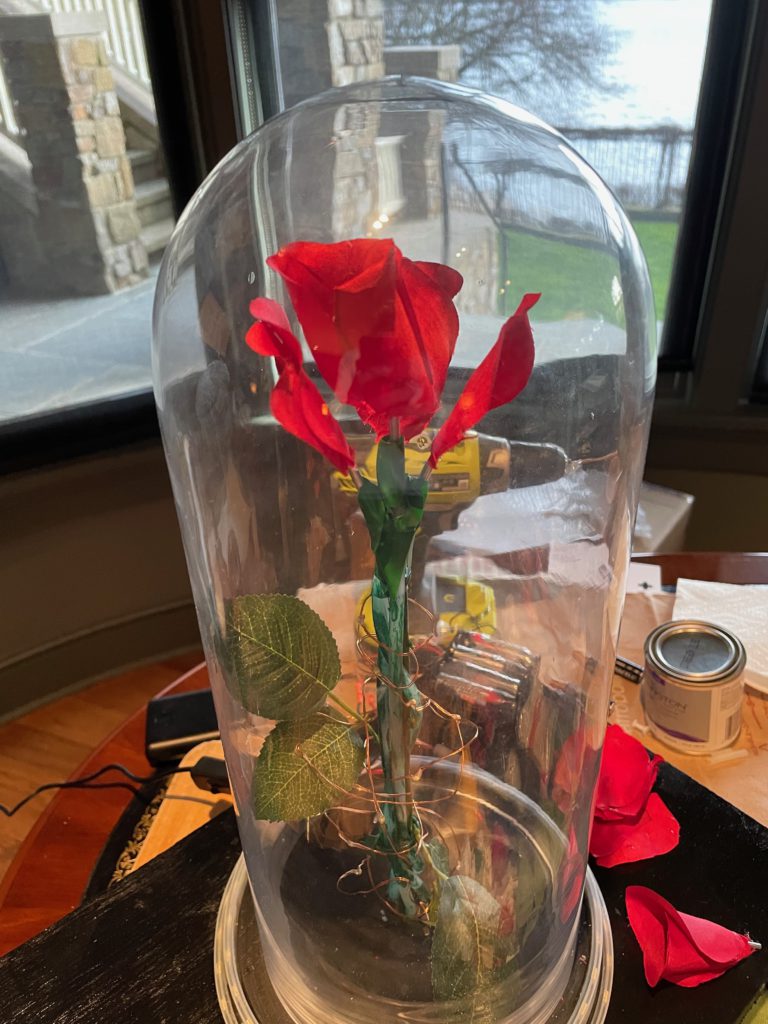
Revisiting the Enchanted Rose project four years later, this time with an open-source build based on Raspberry Pi.
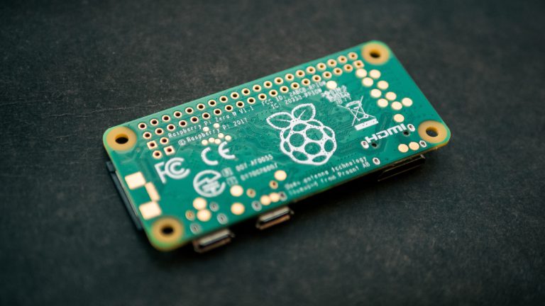
The Raspberry Pi microcomputer is great for building “Internet of Things” devices. This technical post describes the steps to get your Raspberry Pi to broadcast its own local network and bridge to an Ethernet network if available. There are other guides showing how to do this on the Internet, but they are often woefully out of date, leading people down real rabbit holes.
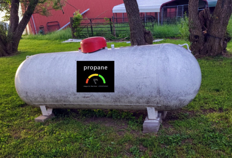
For less than $100, a little coding and a small circuit, you can remotely monitor a propane tank from anywhere.
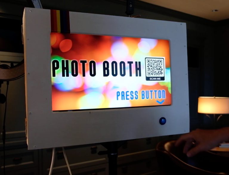
Looking for a fun make-it-yourself project? Why not build a photo booth for your next party? I share a few updates on a #Maker post I made a couple years ago.
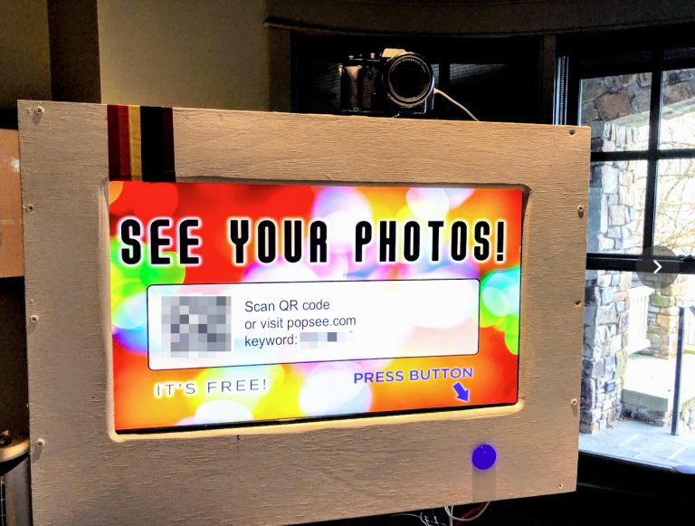
Photo booths are expensive to rent. But if you have a camera and an old monitor lying around, you can make a much more versatile photo booth for less than $100!
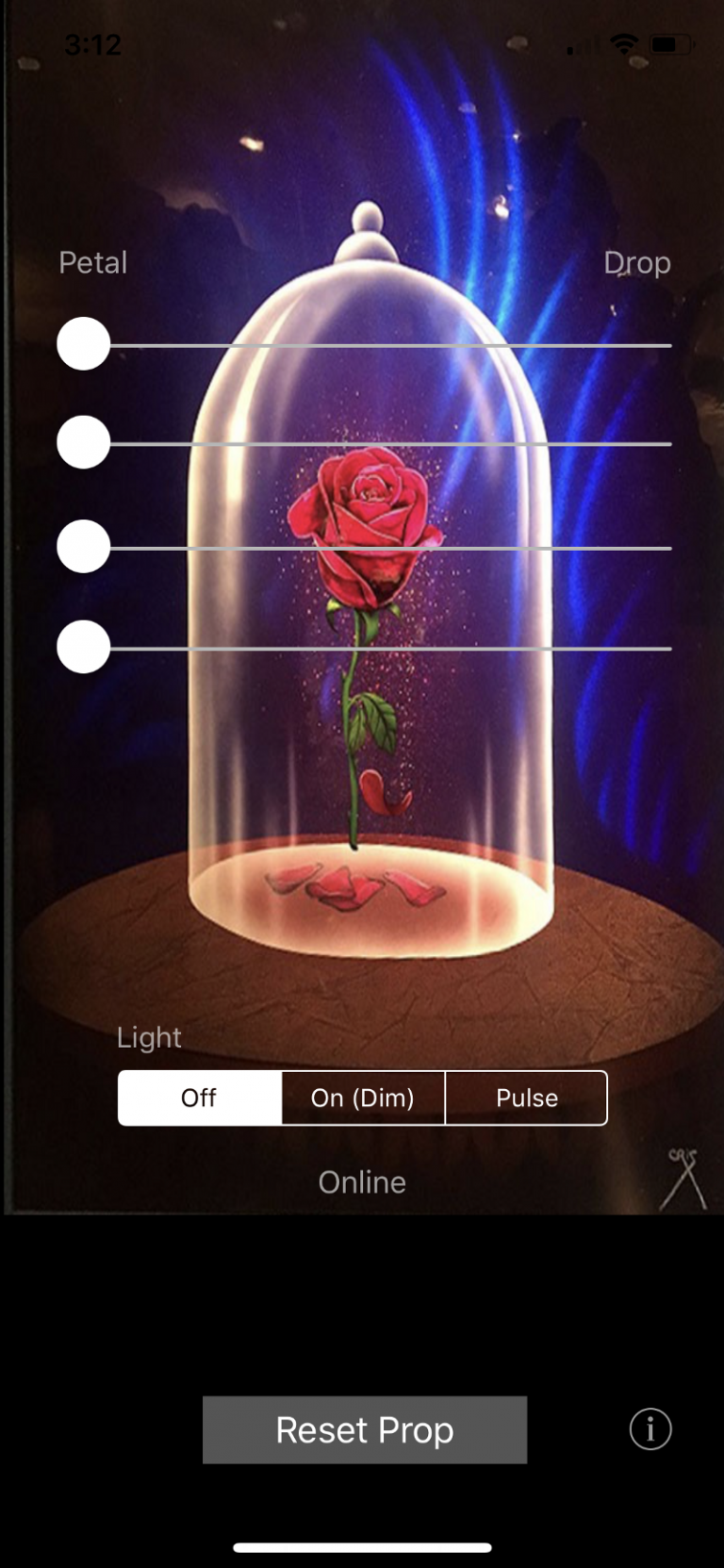
Part 1 of this article covers the basic parts list, code, and assembly. UPDATE (January 2023): I’ve built a version 2.0 of this prop. See “Enchanted Rose 2.0: Raspberry Pi Prop with Falling Petals” for updated instructions. UPDATE (April 2021): The Bluetooth shield used in this Arduino-based project is apparently discontinued. If I were to…
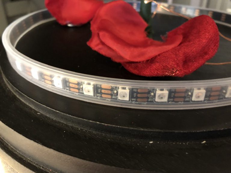
NOTE: There’s a version 2.0 of this project! Follow this link for information on Enchanted Rose 2.0. My daughter is in Beauty and the Beast this spring. So I thought it’d be a good opportunity to test my Internet of Things (IoT) skills using Arduino, Bluetooth and iOS, and build a remote-controlled Enchanted Rose prop…
You must be logged in to post a comment.